PMG booklet page
PMG stands for permanent magnet generator. This booklet describes
how to build one. It was prepared in year 2000 by Hugh
Piggott, for Intermediate Technology Development Group (ITDG),
as part of an overseas
aid project for DfID. It is not confidential; in fact the object
is to disseminate it widely.
The latest version of the booklet can be downloaded in
pdf format here
Feedback is more than welcome. Please let me know what you think.
Steel disks for the pmg can be obained in the UK from Andy
Taylor phone 01305 861001 for £6 each.
--
From: [email protected]
To: [email protected]
Subject: windmills
Date: Thu, 29 Aug 2002
Dear Hugh
I have built a number of axial field pmg's (down loaded
from your excellent website) and I am very pleased with
them. I have recently had a batch of mild steel discs
305 dia. x 6mm with a 65mm hole at the centre as per
plans lazer cut (very nice finish).
and I thought that some pmg constructors or would be
constructors may have difficulty in cutting out or
obtaining such discs. I would therefore be happy to
supply discs at a very good price of six pounds each
plus postage. I hope this could help others to enjoy
constructing there own pmg/windmill as I have. I can be
contacted by e-mail or phone 01305 861001 or snail mail
at 18 Tillycombe Road, Portland, Dorset, Dt51lg,
England. Yours sincerely Andy Taylor
--
The pmg is intended for small wind turbines (although
it can also be used for battery charging hydro turbines). It is of
the 'axial flux' type. Magnets are fitted to steel disks and spun
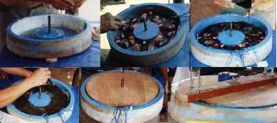
past coils. Here is a picture of magnets on a wheel bearing.
Later I learned to embed the magnets in resin so as to prevent them from
flying off at high speed. All this is covered in the booklet.

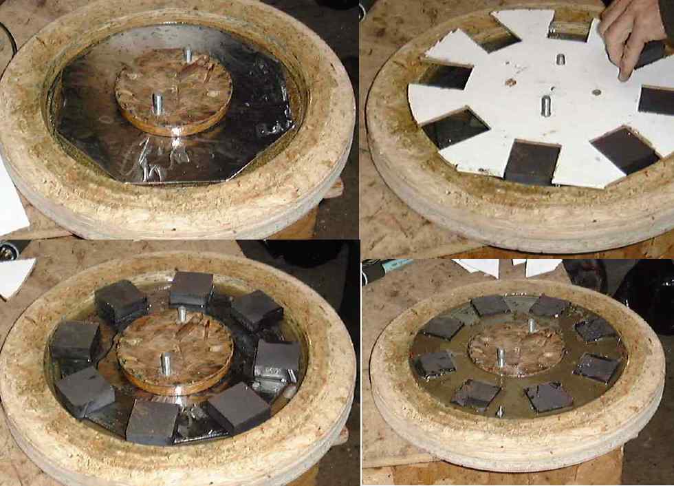
Here's a picture of the stator which is the stationary bit which holds
the coils. The coils are set in resin. Here below the resin
is clear so you can see the coils embedded within. A magnet rotor
passes on each side of this disk and produces AC voltage in the coils.

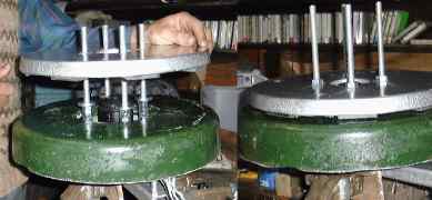
Another magnet rotor fits on top of the stator. Next, in
this early picture, I am spinning the alternator with a power drill to
collect data about the output at various speeds.

Here is a set of pictures detailing the way the stator is cast in a
mould
And here is the rotor casting process:-
Assembly...
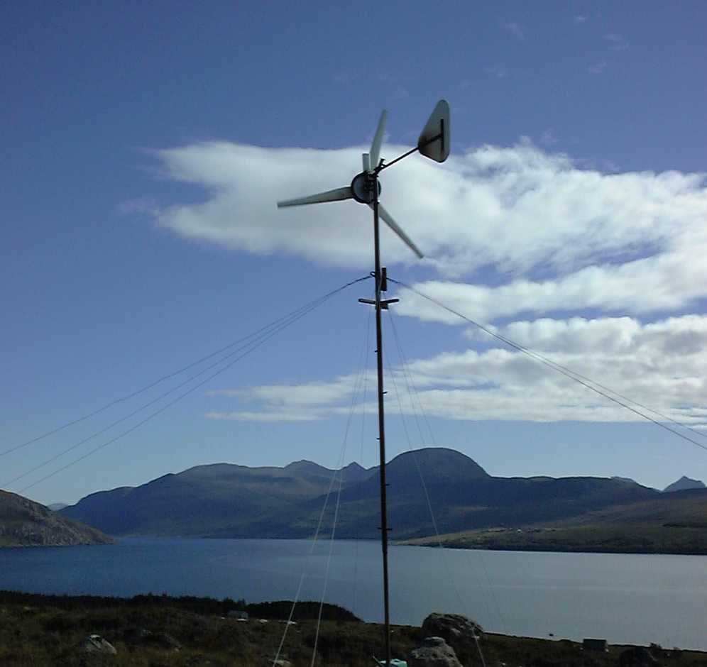
and flight :-)
I am also teaching courses where
you can learn how to do this.
Hugh Piggott