Tools
You will need some or all of the following tools:
saw (+jigsaw+bandsaw..)
chisel (+mallet)
plane
spokeshave
draw knife (recommended)
callipers, compasses
square
tape measure
ruler
pencil
spirit level
drills size 4,8 and 25 mm
Keep your tools very sharp, and always work with the grain of
the wood, to prevent it splintering. Grip the workpiece firmly to
a bench with a G clamp. If a tool judders or sticks, try sliding
it sideways as you cut. A sawing motion like this gives more control.
Materials you need:
3 pieces of wood, 150mm by 50mm, by1150mm long (6" x 2" x 3'9").
Lightweight softwood is the most suitable. Select pieces which are
free from knots or sapwood, with a straight, close grain, and well seasoned
(dry). Imported Oregon Pine is ideal, but expensive.
2 plywood discs, 12mm (1/2")thick, 300mm (1') in diameter, exterior
or marine plywood.
4 off M8x90mm (5/16ths by 3.5") bolts.
48 woodscrews, size10x1.5".
![]()
Start by marking out the pieces of wood. Measurements are made
at the 'stations' of which there are five along the length of each blade,
equally spaced at intervals of 230mm.
Mark the position of each station, and draw a line right around the
piece, using a square.
The left hand end is the root of the blade, and the fifth station is
the tip, at the right hand end of the piece.
The first shaping operation is to taper the blade, so that the tip
is narrower than the root. The width of the first four stations are
145, 131, 117, and 104mm. The width of the tip is 90mm.
Measure these widths from the top edge which is nearest to
you.
If there are any knots in the piece, try to arrange it so that they
are in the triangular piece at the back which you will remove.
You can use a bandsaw for this, or cut the waste out in sections using
a saw and chisel.
Plane the newly cut surface smooth, straight and square.
The blade is beginning to take shape now. The tip moves clockwise,
viewed from upwind, so the leading edge is the one nearest to you.
The front (or windward) face should be perfectly flat at this stage.
If not, then
Plane it flat, checking with a spirit level across the piece, to
remove any twist which may have arisen through warping.
The next stage of the operation is to create a deliberate twist in the
blade. First you must turn the piece around, so that the leading
edge is at the back.
At each station, draw a line on the newly cut face, square
to the front face.
Mark a point on each line, a certain distance down from the front
face (the 'drop').
The drawing shows newly cut face, with the thickness of the wood exaggerated,
for clarity.
join the dots to draw the line of the trailing edge of the blade.
At the root, the line rises to the front face at a steep angle.
The root is left as 150 x 50mm timber for assembly into the hub.
The next carving operation is to put the twist into the blade, using
the line you have drawn.
Lay the piece down with the front face uppermost, and carve away
all the wood above the trailing edge (pencil line), so that you can lay
a ruler between the leading and trailing edges.
When you get near the hub, the wood returns to full thickness in a triangular ramp, as in this front view:
You should now have a piece of wood tapered slightly, with a twisted face hollowed out of the 'front'. This will be the windward side of the blade.
The next step is to reduce the thickness of the piece, so that
it is the correct thickness at each station. The thicknesses are
25,20,18,15, and 11mm at the tip.
Lay the piece of wood with leading edge uppermost, and make
a mark at the correct distance from the leading edge, at each station.
Join the dots with a line.
Do the same relative to the trailing edge,
Now there are two lines, which will guide you as you cut off the waste
wood.
turn the piece so that the front face is underneath, and cut away the waste until you get close to the lines you have drawn:
As you work the piece down to the right thickness, it is more accurate
to use callipers to check the actual thickness at each station. Measure
how many more millimetres need to be removed, then write it in pencil on
the workpiece, at each station.
Resume shaving off the wood.
At the root, be sure to leave the hub disks area untouched, same as
you did with the front face.
You should now have a tapered, twisted blade, with the correct thickness, but the cross section is still a crude parallelogram shape, which is not sufficiently aerodynamic. The final stage of carving your blade is to give it an airfoil 'section'.
Start by feathering off the trailing edge. Plane off wood from
the back until you have a sharp edge, less than a millimetres wide, bevelled
at the angle shown.
Try to make the light shine on the edge, so you can easily see how
much is left to go.
Finally the section needs rounding off into a smooth 'wing shape'.
Take care not to reduce the overall thickness. The thickest part
should be about 25% back from the leading edge.
Draw a line along the back of the blade, 25% back from the leading
edge, and avoid cutting the line.
Keep removing the corners, running your fingers over the surface of the back of the blade or watching the way the light casts shadows as it rakes across the wood. Use sandpaper if you must, but a really sharp spokeshave, set very fine, is lovely to use.
Assembling the rotor blades
Each blade must be cut to a point at the root, so that they will fit
snugly at the hub.
Measure the exact centre of the blade root, and draw lines out to
the edges, at an angle of 60degrees to each edge. Do this front and
back, then cut along the lines
:
The blades can now be laid out with all three roots fitting together.
They are supported in this position by the two plywood disks, one on each
side.
Make pencil marks on the blades, 152mm from each root (front and
back), to help you to centre the plywood disks.
The disks will need pre-drilled, countersunk holes for the screws.
Lay out and drill the screw holes.
I suggest 8 screws on each side of each blade, in the pattern shown.
They must clear the bolt holes, which will be at 38mm radius. The
easiest way to lay out the screw holes neatly is to scribe circles on the
plywood, with compasses, and then walk the compasses around the circle,
marking six equal 60degree angles. Take every second mark as the centre
of a blade, and measure from there.
Clamp the hub together securely, and check that the blades are equally
spaced.
Measuring from tip to tip and adjusting them is the easiest.
Check that the tips are all the same height above the bench on which
the plywood sits.
This will ensure that they 'track' properly (follow each other through
space).
Screw the hub together tightly.
Drill out four 8mm holes for the mounting bolts, equally spaced around a circle of 76mm diameter.
Drilling the bolt holes is best done with a drill press if possible. In any case take care to drill the holes square to the plywood.
Drill the centre of the hub out with a 25mm bit (or similar) to allow cooling air to reach the alternator.
Screw small blocks of plywood to the back of the hub, to permit air flow across the front of the alternator.
While dismantling the hub for painting, take care to mark each blade with a number of shallow holes, and mark the disks to match.
Painting the blades
It may be easiest to unscrew the blades, to paint them and the disks.
The leading edges need special treament, either with epoxy resin or 'leading edge tape'. If you are using epoxy resin, it is best to plane off about 3mm from the leading edges and rebuild it with a paste mixed with epoxy and aluminium powder.
After applying resin if any, prime the wood carefully ,and apply plenty of coats of gloss paint. Sand it well before the final coat.
I do not recommend the use of epoxy coatings unless you are sure that the coating will never be damaged. Water within an epoxy coating cannot escape, whereas other paints will breathe.
I do not recommend varnish, since it degrades much faster than paint in ultra-violet light.
Balancing the assembled rotor.
It is essential to balance the blades carefully. The aim is to ensure that the centre of gravity of the assembled rotor is exactly at the centre of rotation, i.e. the centre of the mounting.
Make a jig like this, from a piece of plywood. Drill a tiny hole at the centre and four 8mm holes, correctly spaced to suit the mounting bolts. Thread a piece of fine cord (eg fishing line) through the centre hole, and lock it with a tiny screw in the hole.
Bolt the jig onto the rotor assembly, and hang it from the cord. It should hang level. If not, then make it hang level, by adding small weights to it.
Pieces of lead flashing are ideal, but old nuts and washers are adequate. Before you screw the balancing weight on for good, check your jig for accuracy:
Remove, rotate and replace the jig in a different position.
The rotor should still hang level.
These instructions were used for a project (the 'windkit') which I entered into with Proven Wind Turbines, based on an alternator which they were able to supply at the time. For more detailed plans and instructions see my other books.
Here is what it looks like now (August 1999), after 4 years in action:
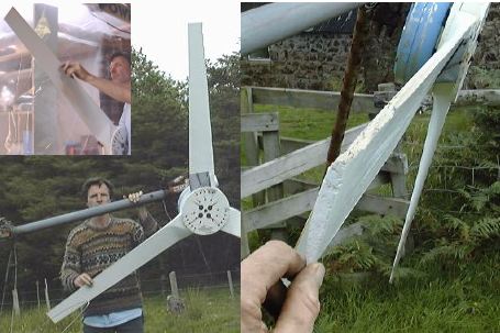
It looks as if I forgot to put epoxy resin on the blade edges!
Otherwise it works fine. The grey patch on the topmost blade is a
piece of lead flashing (used in roofing) screwed on as a balance weight.
Normally a smaller weight will do!