Below is the story of the other machine which did reach fruition.
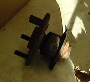
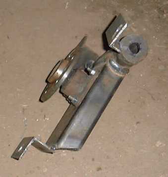
We start with the wheel hub, which came from a Chevy Cavalier (not a Vauxhall
Cavalier but similar in size). The alternator
is loosely based on the axial
flux 'pmg' (permanent magnet generator) which I designed for use in
the developing world. Brakedrums and laminations are not easy to
find in some countries (in fact some people have problems finding them
at all).
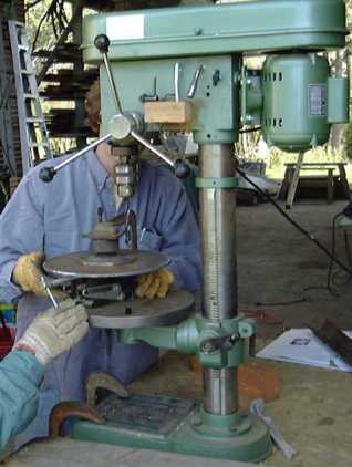
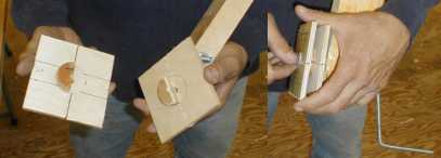
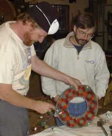
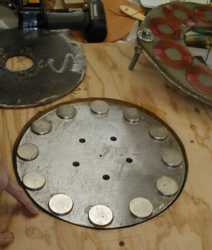
The magnets are glued to two steel disks so that they face each other. See the disks being drilled (5 holes at 1/2") to fit the hub below right. More details of the magnets later.
The stator for this alternator has no laminations
- it is just a disk of coils which sits between the two magnet rotor disks.
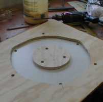
Here (left) is the mould for the stator (simplified from the one described
in my pmgbooklet). On the right you can see the coil winding former,
which is split into two parts for easy removal of the coils after winding.
The coils are circular to suit the circular magnets which we chose in this
case.
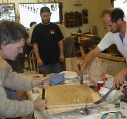
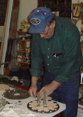
Nora Woofenden helped out with the coil winding.
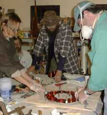
The coils were cast in polyester, watched closely
by Michael McGuiness (a local man,
in the brown hat) who is also building one of this type. Michael
was our 'scrounger' whose task was to find things in a big hurry when we
realised we had forgot to get them before. Thanks for keeping us
supplied Michael! Here we have Kelly and Brian doing the dirty work,
with respirators, filling up the mould with coils and polyester.
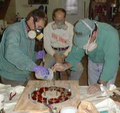
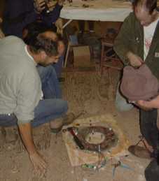
Next day the casting was still soft. We had to heat the mould
up, so as to kick the polyester into action, but after a few hours we were
able to lever off the top and pry out the completed stator. Hugh
Glass and Chuck Morrison inspect the final product. Much easier to
produce than a laminated stator. Hugh Glass is a talented stage hand
from Utah.
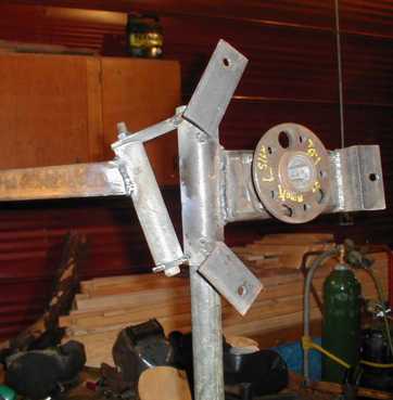
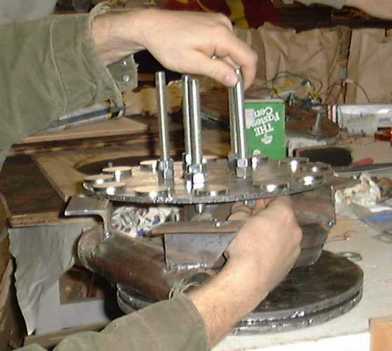
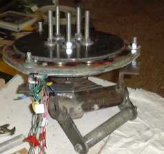
Now that we had the stator we were able to accurately position, and
weld three supporting lugs on the yaw frame (see below).
We placed the stator on a magnet rotor disk and centred it. then
we fitted 3 pieces of steel angle to the stator using 1/2 inch 'all-thread'
or 'threaded-rod' or 'studding'. The all-thread allows us to adjust
the position of the stator so as to place it accurately centred between
magnet rotors with the minimum of clearance. The right hand picture
shows the yaw frame set up on a stub tower, with the tail also attached.
The tail boom is welded to an inclined hinge arrangement designed by Tod
Hanley and Jeff Gilbert.
Meanwhile we fitted the magnets to the rotors.
For test purposes they were 'super-glued' to the steel disks, and then
later we set them in polyester for extra strength. In previous designs
I have used ferrite magnets, but in this machine we used neodymium ones
(NeFB), which are stronger. They are also more expensive but the
price is coming down all the time, so they are becoming a very attractive
option. We used 12 magnets, each 1.5inches in diameter and 3/8inch
thick. This works well with 9 coils for 3 phase output.
We are grateful to Wondermagnet.com
for supplying the magnets. Wondermagnet's sister website Otherpower.com
has a very interesting low tech alternator design using wood. Our
design uses steel which makes it more efficient and also more practical
for permanent duty.
Here is Kelly casting his magnet rotors in a level mould 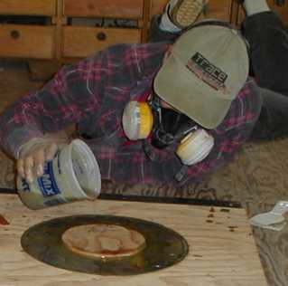
We did a quick test of the alternator - cranking it by hand and measuring
the voltage at a low rpm. It came out exactly as predicted.
Using simple calculations I matched the speed of the alternator to the
speed of the 8 foot diameter wind-rotor (propeller) so that it would run
at or near its design tip speed ratio of 7. We were able to adjust
the cut-in speed of the alternator to suit the blades by careful grouping
of the coil connections.
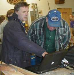
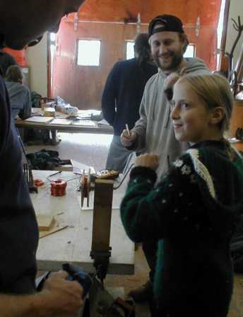
Below I am showing Bob Peterson a design spreadsheet for matching up
the rotational speeds.