Small Wind Turbine FAQ
Hugh Piggott October 2006 - updated
June 2007
This is a collection of questions and my answers over the last few
months.
Pretty random really but I thought they might be
useful.
Much of it relates to my designs
and the technicalities of modifying them...
Themes: general (below), blade production, alternators, electrical,
charge control, tails
General questions
I'm just getting interested in wind
power, do you know of any other good sources where I can
learn the basics?
http://www.windpower.org/en/core.htm
http://www.windmission.dk/workshop/workshop.html
http://www.awea.org/faq/
http://www.wind-works.org/
http://www.otherpower.com/20page1.html
What part can small wind turbines play
in the development of sustainable energy-systems for household use?
This would depend on the location and the needs of the household.
If the location is exceptionally windy, then wind energy is an obvious
option. If there is no grid power connected then small wind becomes an
attractive option. If there is grid power available, then it is
possible to buy wind energy from wind farms using much larger turbines
that are more cost-effective. However his/her small wind turbine
can be connected to the grid if this gives the owner
satisfaction. And there will probably be attractive rates
for selling any energy that he/she does not use.
However this small grid-connected turbine will not be able to operate
without the grid, so it will not serve as a back up to the grid if it
fails. In order to be able to provide backup, it would need to be
of the battery-charging (off grid) type which is less suitable for
grid-connection, being more expensive, less environmentally friendly
and less efficient than the simple grid-connected type.
If the location is not windier than average, then small wind is
probably a waste of effort but there is no reason not to do it if the
householder just wants to do it. There is no reason to drive
around town in a big four-wheel drive vehicle, but people do
that. If they need to buy a small wind turbine, then that is fine
too (even better!). But they need to understand that it will not
save them any money (unless the site is really windy). It will be
less environmentally damaging than a four wheel drive, but it will not
immediately 'save the planet'
====
We've just bought a house right on the
North Sea. With the constant wind/breeze I hope I'm right in
thinking we can maximize the benefits of wind power. I can't seem
to find good info on how much power we can expect from a turbine -
hopefully one that is small enough to bypass planning permission which
might be snaky in our little village in Scotland. Can you put me
on track?
You can find out the annual mean windspeed (in the UK) here.
But beware it may not be that accurate especially in built up areas.
You also need to know the swept area of the turbine. Here are
some estimates of energy production at different annual mean windspeeds
per sq metre of area.
mean
Energy
windspeed per year
m/s
kWh/sq m/year
3
58
4
149
5
280
6
434
7
591
For example if the diameter is 2.1 metres. Swept area is 2.1 x
2.1 x 0.875 = 3.5 sq metres
if windspeed is 5 m/s then the energy per year will be 280 x 3.5 = 1000
kWh per year approx.
1 m/s = 2.2 mph
Do you have any performance data or
projections for the 8-foot machine that
relates watts to wind speed?
I have some data from Guemes Island Store. It is mean windspeed
and mean power as in energy production again.
1 kWh per day at 6 mph average, and 2 kWh/day at 8 mph average.
Or, do you have a tip speed ratio and
a way to use it to get m/s out of rpm
data?
tip speed ratio varies
from about 8 at cut in - 7 mph at 200 rpm
to about 6 at 70 watts - 10 mph at 230 rpm
to about 5 at 500 watts - 25 mph and 450 rpm.
====
I was wondering being new to the idea
of homemade wind power how long is a turbine expected to
last. Also how much, and what kind of maintenance is
involved
in keeping them functioning.
They can last twenty years, but repairs are called for now and
then. It's hard to say how often because all builders are
different as are all sites. I would expect a couple of problems
in the first year, and maybe one per year thereafter. Can be just
a blown diode, or can be a new set of blades need to be carved.
====
Can you use a 24V PMG to charge a 12V
battery, the only consequence being lower efficiency because the
charging current is about half what it would be with a 12V PMG?
The speed would be too low and the blades would stall. They would
be unable to get going.
====
Hey -- Doug and I have been talking
about getting his machine up. What thrust value should we
calculate for with that 8-foot diameter axial field machine when we're
trying to size guy wires?
Working thrusts will be about 60-80 pounds but of course the dynamic
thrust swill be many times this in gusts. I would allow at least
200 pounds, plus whatever factor of safety.
====
How do you get the power from the
alternator to the ground. I guess slip rings of some sort.
Do you have a tried and test diy
solution ?
On the whole I prefer to use cables that drop down inside the
tower. they are simpler and less prone to failure on most
sites. On some sites they are a pain but if the yaw bearing is
stiff and the site is open to steady winds, then wires dropped down
inside the tower will go for years without attention.
===
Blade
I'm puzzled. The traditional
design, used for a century or more on farms in this country to pump
water, has a turbine with many more blades that modern turbines,
including yours. Intuitively, this older design, packed with more
blades and surface area wetted with wind, would seem to be able to
extract more energy per square meter. The largest modern turbines
are monstrous, with only 2 or 3 blades, turning very slowly and leaving
most of the swept area empty for the majority of each rotation.
Are these new designs really more efficient and, if so, why?
You need to understand that power is a mixture of torque and
speed. For pumping you need high torque and low speed. For
generators you need high speed and low torque. It is not possible
to get high torque and high speed because there is not enough power in
the wind for both.
If you use many, wide blades, you will get high torque but the blades
will not run fast enough to operate a generator.
High speed blades are few and slender. It may appear that the
wind could blow between them but this is not the case once they are up
to operating speed. In fact they do a slightly better job of
extracting all the available power from the wind.
====
I have searched
through many of websites looking for a good design and understand
a little of the basics, but I'm not really sure what to choose.
Is carving wooden blades the best
option?
In my opinion yes it is the best material to use and if a pleasure to
work with and stronger than any of the alternatives. But you can
use pieces of pipe with success if that is more attractive to
you. It is hard to find suitable wood and some people find wood
carving a bit daunting.
I also found a site showing how to
make a turbine from pvc pipe, <http://www.mdpub.com/Wind_Turbine/index.html> -good idea?
Well it obviously does work. I would expect the blades to crack
and fall off. There is a very bad stress concentration where the
fixing area ends and the wider bit at the root starts. that right
angle is perfact for fatigue cracks. I am not sure whether he
runs this turbine continuously but I would expect those blades to fail
in strong winds after long periods of running. Also the
efficiency is lower than wooden blades with a better shape. But
they work and may be easier to make so why not?
Should I stick with a
fairly standard design?
I am not sure what you mean by this. Using a well designed
turbine will probably be a better plan than guesswork.
Is there a way I could make a good
turbine from junk materials, sort of like I did with the old fan
blades, instead of carving, etc. from scratch?
Old fan blades can work OK. But if they are twisted then the
twist will be the wrong way compared to wind turbine blades. so
try to use straight blades and then try to get the right setting angle
or blade angle to match the speed you are running them at.
Matching the blades to the alternator is the biggest challenge for wind
turbine design. it makes a huge difference if you get the speed
matching right.
====
Hugh, i have some questions about the
carving of the blades: it's about step three (pages 13 and 14 of
your axial flux windmill plans) and where carving the thickness is
explained. Near the root (where the line marking going from station 3
to station 2 leaves the wood and is going into space) i don't remember
how than the extrados ends up into the root of the blade. Can i draw a
line on the extrados from leading edge to trailing edge that connects
the markings made to determine the thickness?
Yes, that is a good rough guide for when you begin to cut. As you
make progress toward the line you can ignore it and focus instead on
1. Having the correct thickness at the line 30% back from the leading
edge
2. Keeping the back of the blade parallel to the front of the
blade.
The lines are only a guide for when you start cutting. The face
you will cut near to the root will not extend from front to back but
this does not matter because the important things are the two rules
above.
How do I carve the airfoil taper on
the leading edge on the blade?
It's clear how to do it on the
trailing edge, but not the leading edge.
The books show the general shape, but
no measurements.
Should I just roughly attempt to carve
that shape, or am I missing something?
It certainly is not critical. If you wish to be exact you could
make templates based on the shape portrayed but generally a bluntish
shape is all you need. I have seen some pretty rough stuff
working well.
It needs a smooth curve. You can measure the angle at the leading
edge and follow that and then radius the edge itself slightly perhaps.
The problem is that hand carving a precise shape is too time-consuming
to be worth it, given that there is a broad range of acceptable shapes.
If you have ever tried to carry an 8x4
feet sheet of ply wood across a building site, its much more difficult
than a piece of 6x2 inch, on a windy day. So why are all modern
rotors long and narrow, and only have 3 blades. The old farm water
pumps had many blades which looked like square angled pieces of tin
plate mounted to look like a wheel. More surface I thought wood equal
more power ?
More surface area makes more force. But for electricity we need
speed. More speed, less force for the same power. Wind has
a certain limited power. So for high speed we use low force and
narrow blades spinning fast. Old farm pumpers cannot move fast.
I have one very simple question you
may be able to help me understand. Why is the three blade prop so
popular? I understand that it is probably faster but with less
surface area comes less force and with less force comes less torque (at
least that's how my mind works). Would a traditional water
pumping windmill geared for higher RPM be a bad idea? More
surface area = more torque in my mind.
You are right in some things, but you do not understand that role
played by torque. This is a common mistake. Torque is the
not the same as power. Power = speed x torque. At high
speed you get power with low torque. A three bladed turbine
produces power at high speed and low torque whereas a pump produces
power at low speed and high torque. The efficiency is similar,
but the high speed one is usually a bit more efficient. It also
saves on the power losses involved in gearing up to high speed.
Gearing is also a lot of extra hassle and expense.
One thought I had whilst reading
through was I notice you use conventional type blades on your
generators, has anyone ever thought or tried more of a turbine type
affair i.e. a tapered tube to increase air speed with a fan located at
the end ?
No but it has been tried. The answer is that it simply isn't
worth all the extra material involved in building a duct like
that. The wind tends to divert around it so you don't gain as
much as you would think. It is actually more effective to build a
conventional blade rotor with larger diameter, than to make a duct.
Can you use a gearbox on the back of
the propellor to increase the velocity of the shaft which you can then
attach to the alternator or other electricity generator type unit
The reason I suggest this was I saw a
bloke attach a gearbox to a waterwheel to increase the rpm as the water
wheel spindle went very slowly. It was a huge increase something like
1:444!
Why cant you use the same principle
before connecting to the generator/dynamo?
Please advise if this idea has any
validity and if it has what type of gearbox could you use.
Yes this is a common approach to the problem with larger
turbines. The friction in the gearbox and the maintenance and
cost issues make it unpopular with small wind turbines.
===
- How essential is it to use leading
edge tape?
not at all essential.
- If it is advisable, then does it
need to be applied along the full length of each blade?
On high winds sites then use it for at least half of the length.
- How do you apply it? I have found
some which is 2” wide, in which case do you lap it an inch either side
of the leading edge?
yes but take great care to avoid trapping air.
- Does the prop’s rear plywood-disc
seat directly against the front face of the magnet rotor, or against
the four nuts that hold the front magnet rotor – as some pictures show?
Or can the whole assembly be held in place by the nuts on the very
front of the prop?
I ride it on the nuts for better cooling and it allows me to adjust the
blade tracking more easily too.
- I am hoping to mount the machine on
a 12m guyed-tower, but the area where I plan to site it is a little
restricted, so how ‘steep’ can the uppermost guy-ropes safely be. I
have tried to estimate some of the angles from some of the pictures on
your website, and they seem to me to be in the region of about 35-40
degrees (taking a measurement from where the guy joins the tower). Is
this about right? What is the absolute safe minimum?
I would try to use 45 degrees with 76 mm diameter or use thicker pipe
say 89 mm overall diameter for the tower. some people have steep
guys with only half the tower height from the base to the anchor.
This is minimum I would say.
==
Alternator
Am I right in thinking for a 12V
alternator I need to connect something that draws 12V for it to spin at
the right speed? for example 12V worth of bulbs (just to demonstrate to
my teacher)? How does the wattage of the thing attached affect how it
spins, and is this why a heater wouldn't work very well?
OK yes you are correct and this is pretty basic stuff.
The alternator's open circuit voltage is proportional to its
speed. At a certain speed known as cut-in it will produce its
nominal voltage (say 12 volts). If connected to a 12 volt battery
it will produce no power at lower speeds. This is good because it
allows the turbine to spin up. Volts without amps means no power,
so no load on the blades.
If connected to a 12 volt bulb or a 12 volt heater the alternator will
deliver current (amps) immediately. These loads will draw a
current at any voltage. You need to give them the correct voltage
to get the rated power. Or lower voltage for lower power.
Not higher voltage, or they may become dangerously hot.
The blades will work best a certain speed range related to the
windspeed range. This keeps it in its 'power band'. If it
is held too slow then it will stall. If it is connected to a load
that needs a higher voltage it will run too fast and produce very
little power that way either. So it has to be correctly matched
to the load. The variables are many: blade design and
diameter, alternator speed and voltage, windspeed, etc etc...
We design or choose and alternator with the correct power/speed
characteristic for the blades. This characteristic will depend on
the voltage but this is usually controlled in some way, for example by
a battery that more or less sets the voltage for the whole
system/circuit. If we can be flexible about the loads and use
control electronics to adjust the loads then we can run the alternator
at any voltage we choose and we can use pretty much any alternator with
any blades (so long as it can handle the power). But this is the
hardest way to go. Using a battery is the simplest.
-------
What kind of reliability record do the
A-F turbines have insofar as you're aware of ? Any common sources of
failure ?
Mainly not too bad.
Poor welding skills and poor blade balance lead to the tail falling off.
Diodes in the rectifier fail due to poor connections and/or poor
cooling. Or due to lightning or similar surges.
In some cases the bearings can give trouble.
Longer term the biggest issues tend to be with corrosion.
Corrosion of the magnet rotor plates is a very serious issue that can
lead to a major failure in under 5 years. The magnet rotors must
be painted very well or the disk/plate must be galvanised if the
turbine is used in a damp climate.
About
mild steel plate for mounting the magnet. Is this a regular iron
that made from metal iron plate? Or, Is it the standard steel
plate? Just like the white shining steel like the spoon
or folk? Have you tried the aluminum plate for
mounting the magnet? Or just by using regular metal
plate bar? What do you think?
Mild steel is the most ordinary steel you will find. Do not use
stainless steel or aluminium - they are not magnetic and it will not
work.
Can I ask one (probably silly)
question - why do the rotor plates that the
magnets sit on in the axial flux PMGs
have to be made of steel? Is it just
for strength or is it do do with
magnetic field/strength?
The disks need to be made from steel. They are used to carry the
magnetic flux from the back of one magnet to the back of another.
It's part of the magnetic circuit, and steel is the best 'conductor' or
flux.
pleas one question. If I take
stainless
steel disks, instead
of steel disks for the magnets, do I
lose a lot of power?
yes that is a very bad idea because the magnetism needs real
steel. If you like you can galvanise it (zinc coating) but I have
never tried yet.
How do we determine the right amount
of separation between magnets when we are spacing them in the rotors
before cast them in fiberglass.I ask because I have seen some designs
in otherpower.com and the magnets are quiet closer if we compared them
with the distance or space that you used in the generator built in
Peru and Sri Lanka.
If you want to get the most power from a rotor of given diameter, place
the magnets close together. If you want to get the most power
from a given set of magnets, place them far apart. Then you have
room for more copper in the coils and you also get less leakage of flux
between magnets.
I found a great deal for magnets
and ordered them.
Well I just realised that they are not
grade N35 but N42 (US version)... does this affect my turns per coil or
wiring size?
N42 magnets will have about 10% higher flux than N35. This means
that the machine will reach cut-in voltage about 10% slower than with
the N35. This is OK and will mean very good performance in 7 mph
winds, but as the wind increases the blades will be going too slow and
it will stall.
There are various ways to counteract this. You can use 10% fewer
turns in each coil. I doubt if this will allow you to use a
larger wire size as the changes in size are nearer to 25%. Or you
can have a larger space between the magnets and the stator. Again
you could make the stator fatter but there will probably not be a
suitable wire size. Or you could even make the blades 10% longer
by increasing all the dimensions 10%. This would give you 20%
more power in any given windspeed below the maximum but would not
increase the maximum output of the machine.
====
First, if they are the correct size,
am I correct in
assuming that the more powerful the
magnets, the
better? I have purchased some
N50s, capable of
lifting 82 lb. each. Let me know
if you have any
comments.
Well stronger magnets do allow you to build a more powerful machine,
but they are not the only way. It may be more cost-effective to
use a lower grade magnet and build a bit bigger.
Second, is there a good reason not to
use aluminium
magnet wire? It would mean a
great deal less weight
for the coils, but would it work as
well as copper?
I have never heard of it being used. the main drawback is that it
would take up more space. It basically has higher resistivity -
you need about twice the size wire for the same resistance. I
don't think it does work out much lighter even in the end.
Lastly, I see some magnet wire is
available with
square cross section. Given that
this would allow
tighter windings, wouldn't it be worth
the extra cost
and effort if it makes for a more
efficient stator?
It's really down to cost. Yes it packs more copper into the
stator, but there may be ways to get as much in by making the machine
bigger at lower cost.
===
Can I use the ("Axial Flux") plans for
the 8 foot pmg to build a 6 foot version, and do you have any
ideas about winding coils as well as magnet sizing for a six foot
version? How can I work out how many turns I will need in the coils,
what gauge of magnet wire to use, and how many coils I'll need in total
too? I want to build a 12 volt 3 phase wind turbine to charge
batteries in winter when my solar array is idle.
I would suggest using 8 magnets 46 x 30 x 10 mm grade 40.
Rotor diameter 233mm
Six coils. Each coil has 80 turns 1.7mm diameter winding wire.
Connect the coils in star parallel. All the starts to a ring
neutral. You can either use 6 wires out, and a rectifier at the
top, or you can parallel the wires of the same phases and bring 3 wires
down to a rectifier at ground level.
Blades scaled down to 3/4 size compared to 2.4 metre version.
Suggested offset from yaw bearing is 80 mm.
cut in speed 280 rpm. You may find that it is prone to stall if
the wiring to the battery is too thick. It's a bit too
efficient as an alternator for such small blades.
You might do better using smaller magnets which would also be
cheaper. The electrical efficiency would be less but the blades
would be less prone to stalling so overall you might do better.
for example you could use 8 magnets 1 x 1 x 1/2" on 170mm disks.
http://www.powermagnetstore.com/acatalog/Block_Magnets.html
use 95 turns of 1.4 mm wire connected in series/star connection.
I have made an alternator and wired it
delta as described in your brake drum book (yes its a bit old but
I like the drum type) a-f b-d c-e and I notice that it
becomes slightly harder to turn when turning it by hand on the work
bench when no load applied to it. when I connect it star it shows no
increased resistance to turning . if I break a connection say b-d
and connect a volt meter between them it shows a small voltage, is this
normal or are the windings not electrically balanced?
Yes this is the main disadvantage of using delta connections.
With a hand-built alternator it is very unlikely that the phases will
be perfectly balanced in voltage and phase angle (timing), so there are
some parasitic currents around the delta itself. This can make it
hard to start up. Once the rectifier starts to work there will be
third harmonic currents as well. So delta is less efficient than
star.
I generally recommend using fewer turns of thicker wire and connecting
them in star rather than using delta if you have a choice.
Oscar can only find ferrite magnets and asks if we could get more power
by using laminated steel in the stator.
Ferrite magnets are probably quite cost effective but mess efficient
that neodymium for their size so the machine is likely to have lower
peak output and the coils will need to be re-designed. I probably
should include a ferrite magnet design in my plans to show how to do it
or he can refer to my free PMG document on the web page.
====
A lot of people ask me why I don't put
a core into the coils in the stator in the axial flux machine.
The advantage of using a core is obvious. A core would reduce the
reluctance of the magnetic circuit by reducing the air gap that the
magnetism has to jump across, and this would result in higher
flux. Higher flux would mean more voltage from the stator at a
given speed, or the ability to produce the same voltage with fewer
turns of wire and hence lower electrical resistance. Basically we
would have a more powerful alternator or at least a more efficient one.
However this performance boost comes at a price. The magnet
blocks would be attracted to the cores in the coils. This would
result in heavy 'cogging' torque, where the rotor jumps from one coil
to the next. Even if this can be smoothed out by clever
positioning of multiple units out of step, there will still be some
magnetic drag on the rotors due to the losses in the cores. This
would affect start-up and low windspeed performance. Even
using laminated cores there is some loss to eddy currents and some loss
to hysteresis.
So my answer is that although you can get more power from a given set
of magnets by using a core in the stator, magnets are getting cheaper
now, and I prefer the simpler, smoother solution with no cores and no
start-up problems.
====
A person that has problems trying to
find the appropriate wire size says that he found a place where they
have 1.5mm or 1.25mm diameter wire, not the recommended 1.4mm for
the 1.2m generator. Which of the two sizes would be the one to be
used? With the same turns per coil?
He should use 1.5 diameter, the same number of turns, but the stator
casting needs to be thicker. Instead of 11 mm it needs to be 13
mm thick.
Are the diodes for the small 1.2m
machine the same as for the 2.4m big one?
Yes I usually buy the 35 amps diodes for all turbines. It is
possible to save some pennies and buy lower current diodes. But
there is more safety factor if the diodes are rated 35 amps and 800
volts or so.
You say that it must be 'Flexible wire
with high temperature insulation 0.75mm bundled in a protective sleeve'
Can you
give me the name and phone
number of a place where I can buy it?
I don't know where you are :-)
Here in the UK I prefer to use "tri-rated flex". But even pvc
coated
flex would work fine I am sure. Automotive stuff would be fine.
====
I'm a bit confused on the
specification of the correct cable to use in wiring the neutral ring in
the stator and output from the tails of the windings. In your book you
specify:
"Flexible wire with tough,
high-temperature insulation" 14 gauge or 2.5mm"
does the 2.5 mm refer to the diameter?
no, in the case of other types of wire the size is a cross sectional
area. 2.5 sqmm is a common size.
What type of current and voltage
should this cable be able to handle? e.g 30amps 1000volts?
(My windings are 1.6mm magnet wire)
To be honest it is not that critical, but I recommend the neutral and
the tails should be as big as the magnet wire in other words 2
sqmm. 2.5 is a common size. I like to use tri-rated flex
but ordinary pvc covered flexible cord will do.
==
My question
is what is the purpose of the use of talcum powder in the resin?
I was unable to find the answer in the book or on my own in talking to
people in the trade of using the fiberglass resin.
Talcum powder is used in the resin casting for 4 reasons:
1. It moderates the heat of the reaction, so that the casting does not
get so hot and therefore does not shrink and crack as it cools.
Nor is it so likely to overheat during the pouring process and set
prematurely.
2. It alters the thermal characteristics of the casting - makes it
better at conducting heat when the coils are working hard, and keeps
the coils cooler, allowing them to carry more current safely.
3. It is much cheaper than resin so it saves on cost.
4. It thickens the resin so that it does not leak out of the mould so
fast if there are minor leaks around the edges.
====
Hugh,
My wind generator project is moving
forward nicely. I’ve reached the steps where I’m starting to
fiberglass things in and was curious why do you add Talcum powder to
the mixture? Is it a problem if I just use fiberglass resin only?
In a practice mix, I found it very difficult to get the Talcum
powder mixed in without creating clumps and introducing air bubbles.
Talcum powder is important, yes, Mainly it is there to moderate
the heat of the reaction. Without fibreglass the mix tends to
heat up too much in the mould, and when it cools it warps or
cracks. It an also start to cure prematurely. Talcum powder
also makes the mix less fluid so it does not tend to run out of the
mould so easily and it is also a lot cheaper than resin. Putting
it id does introduce a bit of air, but so far I have never found this
to be a problem in fact.
======
I'm thinking of building a 12' wind
turbine. the site is a long way from my house so I want it to have a
high voltage. your plans give specs for 12 volts. two wires, 25 turns
#13 awg. I assume one wire, 50 turns same gauge wire would give me 24
volts. in your table on page 4 of how to build a wind
turbine, the relationship between wire size and the number
of turns doesn't seem exactly liner. Since I'll be producing
AC courant it makes sense to start with a high voltage and
step it down at my house. Do you have any reconditions as far as
wire size, number of turns per coil, expected voltage, how high is
reasonable to go, and transformers. I've also noticed that for
some alternators you specify different strength magnets. for the 12'
you specify N 35 magnets. why not stronger magnets. I realize that the
alternator is designed to work with the blades. I don't want to build
something that is out of balance.
I love wind mills and I love
building things and I think that your book and the whole concept of
building a windmill including carving blades and making an
alternator is the coolest thing ever. WOW!
Broadly the number of turns is proportional to voltage but in some
cases the high rectifier volt-drop at 12 volts skews it, and the
availability of wire in certain sizes.
For 120 volts you could use 220 turns maybe.
If you are using transformers you have the advantage that you can use
tappings to do fine adjustment to speed. The danger is of running
too fast at cut-in or of stalling in stronger winds from being too
slow.
You may find that the turbine has problems starting up when connected
to the transformers. Use a relay to disconnect them at low
speed. You can run the relay off a second rectifier or even
perhaps directly off the AC of one phase (but this will buzz).
======
Just received your plans how to build
a wind turbine, thanks
On page 49 you have plans for a 10
foot, 24vdc unit..
Is it possible to change the windings
to create a 12vdc unit
with the same 9 coils. if so could you
email me with the
wire size and the number of turns?
I would suggest 105 turns in each coil. Use 15 ga wire or 1.4 mm
diameter. A single wire in the coil (not 2 in hand) But the
3 coils are in parallel. You can either parallel the 3 coils in
each phase and bring them down to the rectifier in 3 wires, or you can
put nine wires into the rectifier as in the ten coil version. the
latter is slightly more efficient unless the 3 coils are truly
identical in shape and perfect in location.
---
Electrical
Can your generators be linked to
supply the grid when its very windy ? I believe there are lots of
electronic gadgets for phasing etc or is the cost too high?
Yes they can be linked. This technology is advancing very
fast. The preferred solution is the SMA 'windy boy" inverter.
Can I mention 3 phase?
yes of course. I normally use 3-phase. But 3 phase does not
necessarily mean high power and volts. Car alternators use
3-phase.
What is done to prevent the twist of
the out put cable as the turbine changes direction?
the cable will twist. My philosophy is to make the cable
sufficiently robust and flexible to accommodate several years of
twist. On sites with a certain kind of turbulence, this does not
work and you either need a plus and socket to untwist it periodically
or you have to fabricate sliprings. However these have to be well
made or they cause more problems than the cable.
I have been enthusiastically building one of your design generators (8
foot version) and all is going well, however I was a little confused
about the type of cable used for the tower drop! Is there a
particular cable I can use with anti twist capabilities and if so do
you have a supplier, or is the twisting of the cable not as big a
problem as I am imagining ???
The amount of twist depends a lot on the site. But if the yaw
bearing has a little friction as is normal and the site is good (not
too turbulent) then twisting should not be a problem. check for
twisting from time to time and if it looks like damaging the cable then
disconnect and untwist the windmill in calm weather.
I would recommend the use of single wires rather than a combined
cable. Flexible wires are best. I like 'tri-rated' flexible
wires here in the UK. Expensive but the insulation is very tough.
Building of the wind tubing is now
complete, and 12 metre pole is up and guyed, what i want to know is,
what size fuses do i use on the ammeter, volt meter, and between
inverter and charge controller., and where can i get them from ,
the system is 24 volt. ( pic page 43)
Generally speaking the fuses need to be coordinated to the cables you
are using so there is no danger of fire. for functional reasons
the fuses also need to be large enough that the normal operation of the
system does not blow them. Usually a 1 amp fuse if fine for the
voltmeter. For the inverter, follow the instructions.
Similarly the charge controller will have a rated current and the wires
should be sized large enough that fusing is easy for that.
The wind turbine fuse is a more difficult case. In theory the
current should not exceed about 20 amps, but in reality it may reach
high levels (50 amps) at times and it is undesirable if the fuse blows,
because then it will overspeed. It is therefore a good idea to
have thick cables and avoid short pieces of smaller sizes without good
cooling. High temperature insulation can allow the use of smaller
wires. If the wires become twisted then there is a good chance of
short circuit and blowing the fuse. In such cases you need to
apply the brake switch and wait for suitable conditions to untwist the
wire. Normally it should be untwisted before this happens.
Forklift truck fuses are available from RS and Farnell on the
web. Automotive fuses can also be good but beware that they have
limited overload tolerance.
The generator i have at the moment is
a lister start a matic, of 2 1/2 kw, charging 2 x 200amp hr batteries,
(fork truck batteries), the charger is 50 amp, working 12 hours
on and 12 hours on inverter, can i connect my morning star ts 45
, straight onto this set up, would there be a problem when generator
and charging, and the wind turbine going as well, or would the charge
controller prevent any problems.
The charge controller will prevent battery problems but you may find
that it starts to dump power into a heater when the generator is
running. This may not be fuel-efficient. You maybe able to
get around this by adjusting settings. You can even use a relay
off the generator to adjust them for you if you can cope with the
complexity. Switching a diode or two into the battery voltage
sensing circuit of the controller can be effective in preventing it
from dumping when the generator is charging hard. Much depends on
your battery management strategy.
===
I am contacting you with regards
to the booklet called 'How to build a Wind Turbine'. 8ft 8oowatt
February 2004
page 39 brake switch. What sort of switch
Single pole changeover (2-way) switch capable of carrying the full
current say 50 amps. Not that easy to find actually. You
can also simply use a system of disconnecting and reconnecting to the
negative wire. this is easy with a bolt and lug connection
system, and wing nuts on the bolts.
What size blocking diode
this is optional. It is good for preventing over-voltage during
the process of changeover but in the case of 12 volt systems the max
voltage is only about 50 volts which is not life threatening.
What size fuse
At least 50 amps for 12 volts. Actually it is determined by the
cable you have chosen and must be chosen so that this cable cannot
overheat.
Where to get a trace c-40
I can sell you one. Nowadays I prefer the Morningstar Tristar 60
controller for 12 volt applications. Cost is £140 plus
delivery and VAT.
====
I am currently building a 10 ft dual
rotor pmg, I may be getting ahead of myself but am considering putting
as much power as possible into water heating elements
Heating is usually less valuable energy than electricity so I normally
use it to dump unwanted power myself. But a battery etc is extra
cost and hassle if you are on grid. These turbines are rather low power
so they work well for heating water but will not make a big impact on
space heating.
I am wondering whether it is more
efficient to use your taco control circuit with wild ac
or rectifying to battery storage and
dc to heating elements with a charge controller + dump load
my system is wound for 24 v 3
phases
what is the best arrangement for connecting three phases to heating
elements after taco cuts in and how does affect the pmg loading v
furling
I would be interested to know what you
consider to be the most efficient use of wind generated power
The tacho triac system is normally used with about 200 volts and
multiple small heating elements. It won't really give much more
heat than a battery charge controller, although in theory you should
get better alternator efficiency by operating at varying voltage in
stronger winds (which is not feasible with battery connected
systems). I would recommend using a battery and a charge
controller for simplicity and to provide a stable electricity source
for other purposes unless you have no interest in electricity as
such.
Charge controllers like the Morningstar Tristar 45 only need one
heating element and they control the amount of power diverted to heat
in the load. This is simpler and smoother than switching on and
off multiple small elements.
===
Battery & charge
controller
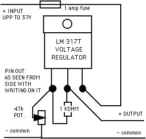
I am currently working on the shunt
reg cct but am
slightly confused about its setup. I
assume it is designed to shunt power
away from the battery strings when
they are fully charged to prevent
damage? If this is the case could you
tell me in what way you would expect
to setup the presets please.
good point. Nobody has asked that before.
You can either wait until it is windy and do it by trial and error, or
you can use a variable voltage supply. The circuit I use is shown
below. the pin-outs are as seen from the side with the
writing. You may need to fix it to a small heat sink.
I also assume that I would need to
source a controller to equally ensure
the battery strings do not get too
discharged to prevent permanent damage.
Yes if you are not able to supervise it to some degree.
supervision is usually better because it causes less disruption.
Use less power when the battery voltage falls. Your inverter will
cut out at some point anyway. This is usually automatic to
protect the battery although the voltage it happens may be quite low.
I am building your charge controller
circuit. I am not an electrical genius and admit i really
don't understand how it works. But i do have two questions---one--once
hooked up to a good stable power supply --what is the proper procedure
for adjusting it.
I would normally try to get it to turn on at 14.5 volts and turn off at
13.5 volts. The capacitors slow things down. I would set
the voltage at 14.5 and then when it has had time to settle I turn the
10k potentiometers very slowly until it clicks on. then I turn
the voltage down slowly until it clicks off. If the gap is too
small or too big then I adjust the 100k pots to adjust the
hysteresis. then I have to set the 'on' point again
usually. I am not too bothered about the off point but if it is
too close then it switches too often and wears out the relays. If
it is too low then it dumps for too long and discharges the battery.
And what voltage would you recommend
it be set at --high and low? for a 12 volt system using 4
batteries.
Depends on battery type. "flooded' batteries with acid in liquid
form I would set higher than sealed batteries. Traction batteries
you could set as high as 15 volts if they do not spend a lot of time
fully charged. Normally 14.5 volts on and 13.5 volts off works
fine.
The comment that inspired me to write
related to your dislike of batteries. I too don't like batteries
either. With that in mind, I have been looking into other energy
storage techniques.
I have been thinking about this for a
bit but haven't gotten it past the idea stage as of yet but I wonder if
you might comment on the concept.
The idea I have it to setup a test
system that uses a windmill/turbine to turn a compressor and store the
energy as compressed air. On the generation side I was thinking of
running generators off of air turbines, possibly little ones where the
power is actually needed. Distribute the compressed air via high
pressure hoses and then generate the power as needed on the spot.
The main problem here is the low efficiency due to loss of heat in the
storage vessel. I think it can work well in large underground
stores and is use for such in gas turbine plant in Texas using oil
wells that are empty) but on the small scale it is hard to see how to
deal with the thermal losses.
I am now looking at the homebuilt
battery charge controller – both on your website and in the book.
Please could you answer a few questions?
sure.
1. The booklet
suggests 2 circuits are required whereas the site seems to indicate one
will do the job- is this just dependent on the rating of the
relays/loads?
More circuits makes for smoother operation. Voltage fluctuates
more slowly and the relays last longer by switching less often.
2. Are any changes
required (apart from the dump loads) for the smaller turbine?
No. I would use 2 small dump loads.
3. Would the idea
be to set the 10K pots so that the dump loads come in at e.g. 14V and
15V
and the 100K (500K) pots to turn the dump loads off at X and Y volts?
The setting of the 100 k pots is the feedback and it determines the gap
between on voltage and off voltage. Set it in a mid range
position. Set the 10 k so that the load comes on at about 14.5
volts. Set both the same more or less. One will come on
first but they are both at 14.5 volts or thereabouts. As the
volts fall, the relays should turn off at about 13.5 volts.
If this is not the case then you can do some fine tuning with the 100k
pot and then possibly adjust the 10 k again.
4. My understanding
is that without a charge controller the generated DC voltage is held
down by the battery.
Yes, this is always true. the charge controller just influences
the battery's diet.
Tail
I do not understand if the tail should
be welded at a vertical
angle or if this even matters.
Also how do I know how the
length of tail, area of tail, angle
offset of the tail, and
weight of the tail will interact to
overcome the friction of
the pipe and the gravity of the tail
weight at the correct
wind speed. Any assistance you
could provide would be greatly
appreciated.
The tail vane can be mounted off-vertical and this may have some effect
on the system but not much. I try to keep it vertical for
aesthetic
reasons.
Length and area need to be sufficient for it to work as a tail and to
hold the rotor into the wind. This will depend on rotor size,
offset
and also on yaw bearing friction.
The angle of offset of the tail is to counterbalance the force of the
rotor in normal winds. It is not critical.
Weight of the tail directly controls the maximum power output.
Friction of the pipe influences the stability of the system and the
accuracy. A little friction is not bad, but a lot will mean that
the
tail tends to get stuck at low output when wind drops a bit.
Other (more important) key factors are the angle from vertical of the
hinge ( which has the same effect as weight) and the orientation of the
hinge seen from above. The hinge points a little sideways (side
angle)
and a little backwards (back angle) on the turbine. The side
angle
influences when it starts to furl, and the back angle controls power in
stronger winds.