BLADES
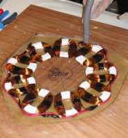
COILS AND MAGNETS
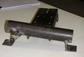
STEEL WORK
ASSEMBLY AND TESTING
MAIN PAGE
|
BLADES |
COILS AND MAGNETS |
STEEL WORK |
ASSEMBLY AND TESTING |
MAIN PAGE |
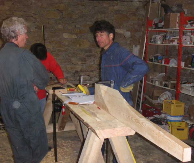
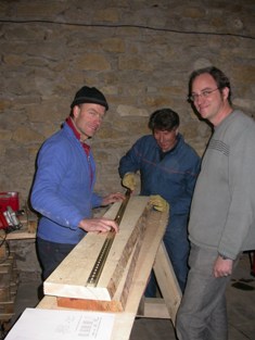 Joris, Serge and Olivier.
|
|
(from centre) |
|
|
|
|
|
|
|
|
|
|
|
|
|
|
|
|
|
|
|
|
|
|
|
|
|
|
|
|
|
|
|
|
|
|
|
|
|
|
|
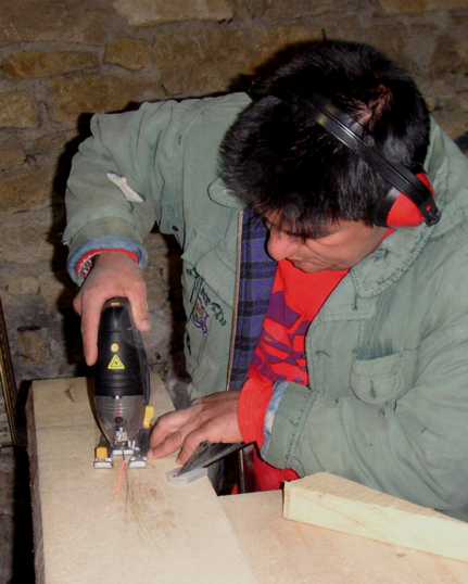
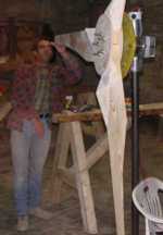
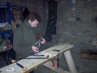
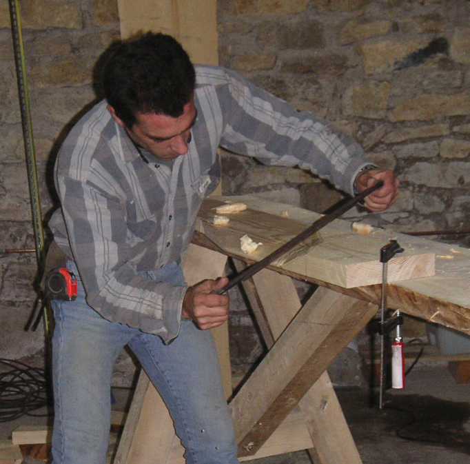
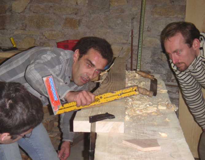
Joël cutting the basic shape with a jigsaw. This is rather
slow and we mostly used a circular saw.
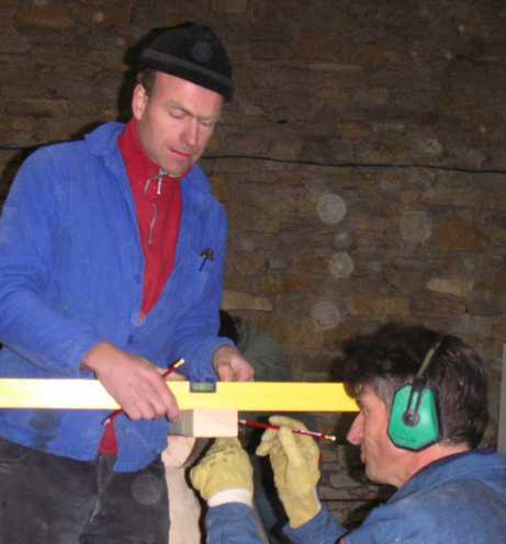
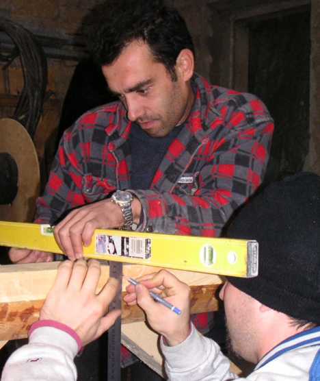
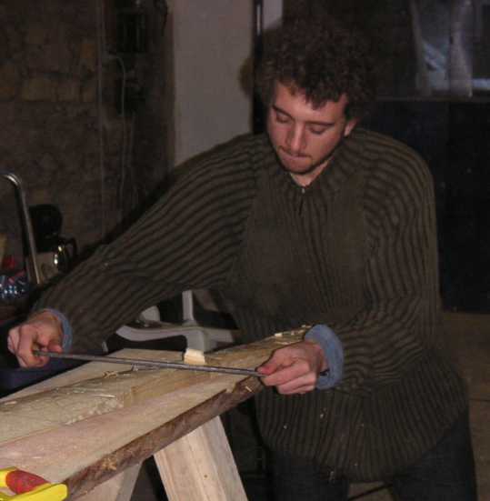
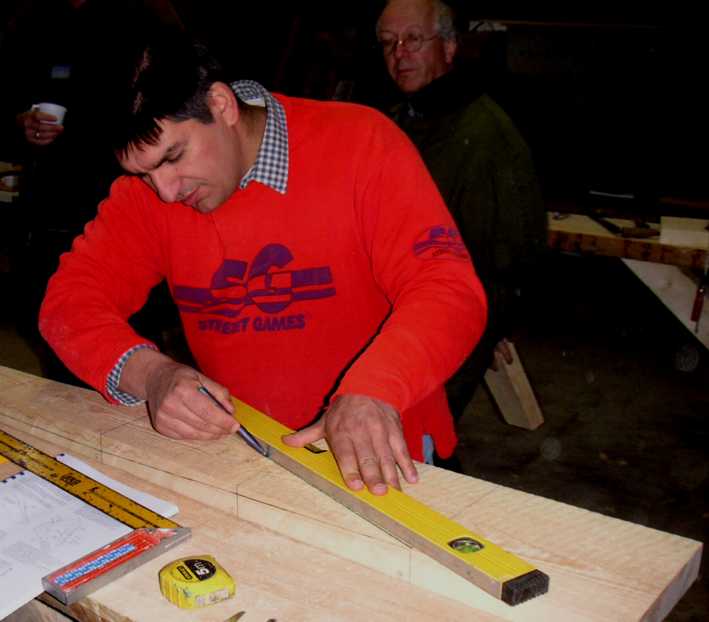
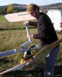
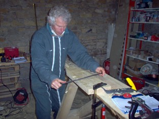
In the end, what matters is that the blade should be the correct thickness
at a point 30% away from the leading edge, and the back should be parallel
to the front until it is later carved into a nice curve.

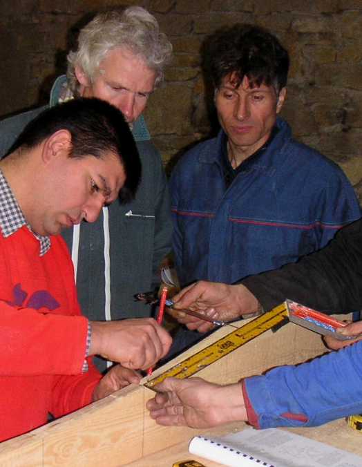
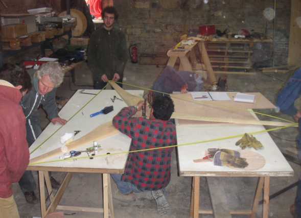
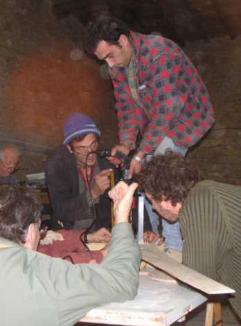
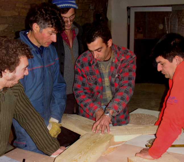
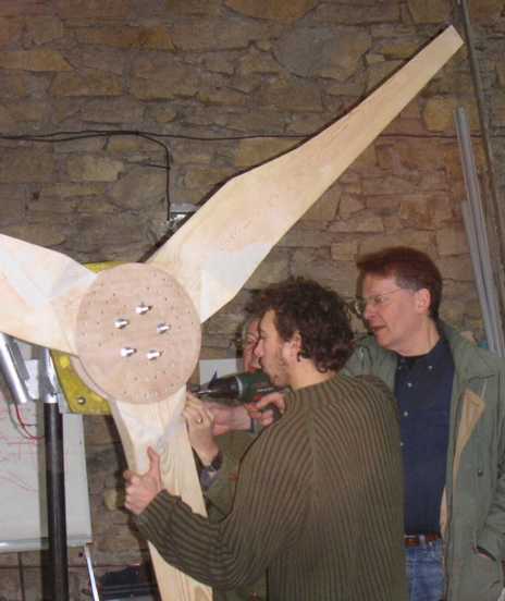
Manu and Giorgio assemble the hub.
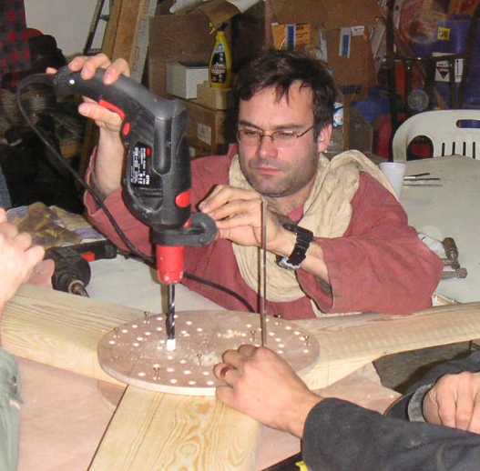
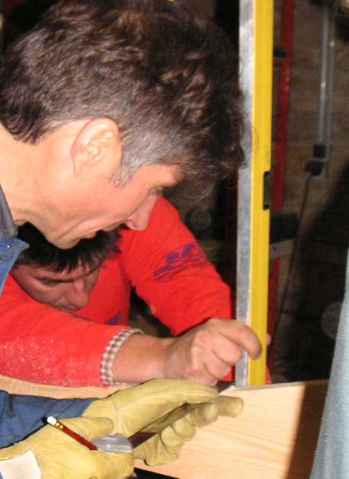
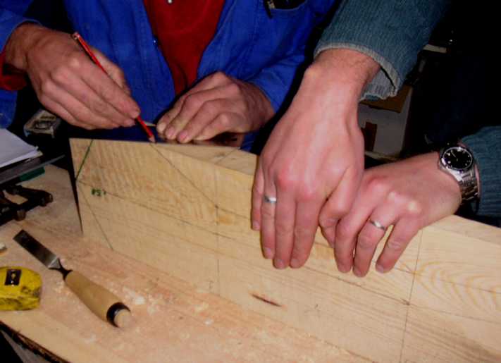
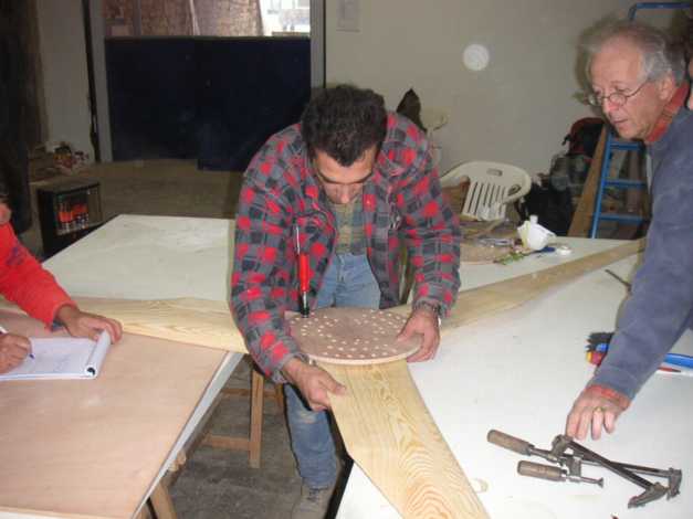
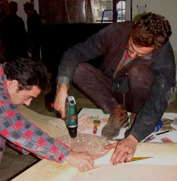
Marking the bolt holes through the rear disk.
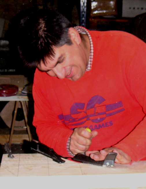
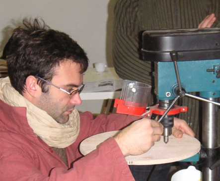
Manu drills out clearance holes in the blades for the bolts.
Thomas inserts screws.

Yves and Benoît fit a balancing weight.
|
BLADES |
COILS AND MAGNETS |
STEEL WORK |
ASSEMBLY AND TESTING |
MAIN PAGE |